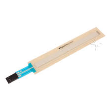
linear potentiometer

A typical single-turn potentiometer
|
|
| Type | Passive |
|---|---|
| Electronic symbol | |
A potentiometer is a three-terminal resistor with a sliding or rotating contact that forms an adjustable voltage divider[1]. If only two terminals are used, one end and the wiper, it acts as a variable resistor or rheostat.
The measuring instrument called a potentiometer is essentially a voltage divider used for measuring electric potential (voltage); the component is an implementation of the same principle, hence its name.
Potentiometers are commonly used to control electrical devices such as volume controls on audio equipment. Potentiometers operated by a mechanism can be used as position transducers, for example, in a joystick. Potentiometers are rarely used to directly control significant power (more than a watt), since the power dissipated in the potentiometer would be comparable to the power in the controlled load.
Applications.
Potentiometers are rarely used to directly control significant amounts of power (more than a watt or so). Instead they are used to adjust the level of analog signals (for example volume controls on audio equipment), and as control inputs for electronic circuits. For example, a light dimmer uses a potentiometer to control the switching of a TRIAC and so indirectly to control the brightness of lamps.
Preset potentiometers are widely used throughout electronics wherever adjustments must be made during manufacturing or servicing.
User-actuated potentiometers are widely used as user controls, and may control a very wide variety of equipment functions. The widespread use of potentiometers in consumer electronics declined in the 1990s, with rotary encoders, up/down push-buttons, and other digital controls now more common. However they remain in many applications, such as volume controls and as position sensors.
Theory of operation.

The potentiometer can be used as a voltage divider to obtain a manually adjustable output voltage at the slider (wiper) from a fixed input voltage applied across the two ends of the potentiometer. This is their most common use.
The voltage across RL can be calculated by:
- {\displaystyle V_{\mathrm {L} }={R_{2}R_{\mathrm {L} } \over R_{1}R_{\mathrm {L} }+R_{2}R_{\mathrm {L} }+R_{1}R_{2}}\cdot V_{s}.}

If RL is large compared to the other resistances (like the input to an operational amplifier), the output voltage can be approximated by the simpler equation:
- {\displaystyle V_{\mathrm {L} }={R_{2} \over R_{1}+R_{2}}\cdot V_{s}.}

(dividing throughout by RL and cancelling terms with RL as denominator)
As an example, assume
- {\displaystyle V_{\mathrm {S} }=10\ \mathrm {V} }, {\displaystyle R_{1}=1\ \mathrm {k\Omega } }, {\displaystyle R_{2}=2\ \mathrm {k\Omega } }, and {\displaystyle R_{\mathrm {L} }=100\ \mathrm {k\Omega } .}


Since the load resistance is large compared to the other resistances, the output voltage VL will be approximately:
- {\displaystyle {2\ \mathrm {k\Omega } \over 1\ \mathrm {k\Omega } +2\ \mathrm {k\Omega } }\cdot 10\ \mathrm {V} ={2 \over 3}\cdot 10\ \mathrm {V} \approx 6.667\ \mathrm {V} .}

Due to the load resistance, however, it will actually be slightly lower: ≈ 6.623 V.
One of the advantages of the potential divider compared to a variable resistor in series with the source is that, while variable resistors have a maximum resistance where some current will always flow, dividers are able to vary the output voltage from maximum (VS) to ground (zero volts) as the wiper moves from one end of the potentiometer to the other. There is, however, always a small amount of contact resistance.
In addition, the load resistance is often not known and therefore simply placing a variable resistor in series with the load could have a negligible effect or an excessive effect, depending on the load.